LASER DIODE MODULE MANUFACTURING
Tutorial on Optical Fiber Coupling and Bonding of Internal Parts
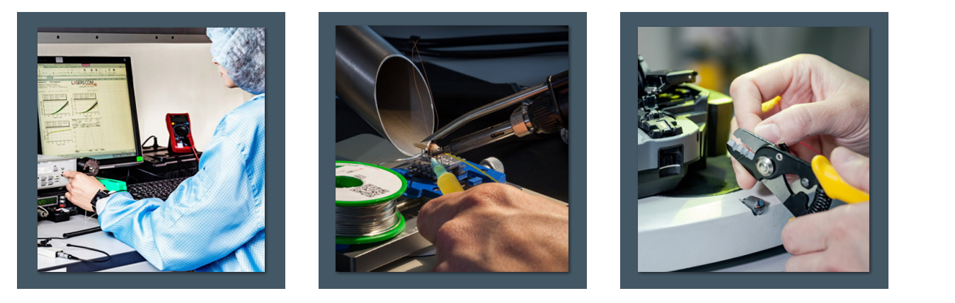 images courtesy of LASERCOM LLC
Author: A. Andryieuski, LASERCOM LLC and Technical University of Denmark Author: V.F. Andryieuski, LASERCOM LLC Editor: Bob Spetz, Laser Lab Source Updated: January 25, 2021
QUICK NAVIGATION:
- Introduction
- Laser Diode Development
- Optical Fiber Development
- Laser Module Performance Requirements
- Coupling Light to an Optical Fiber
- Bonding Internal Laser Diode Module Components
- Laser Diode Module Selection Criteria
INTRODUCTION:
This tutorial was authored by LASERCOM LLC, a Laser Lab Source Marketplace Partner, and edited by LASER LAB SOURCE. In this tutorial, we review and explain two critical aspects of laser diode module construction. First, we explore and explain the key technologies involved in coupling laser light from the semiconductor laser diode into an optical fiber. Second, we review the primary methods of bonding the internal components in the module.
The semiconductor laser and optical transmission fiber are two of the most important technological discoveries of the last century. Both have had an immeasurable impact on technology and societies around the world. In the year 2000, the Nobel Prize in Physics was awarded for developing semiconductor heterostructures used in high speed opto-electronics, and in 2009 for groundbreaking achievements related to the transmission of light in fibers for optical communications. In this article we consider two important aspects of laser diode module assembly: efficient light coupling to an optical fiber and bonding the parts of a laser diode module.
LASER DIODE DEVELOPMENT:
The first laser diode samples, developed in 1962 by the group of R.N. Hall, were GaAs homostructures which were operated at cryogenic temperatures in pulse mode. In 1970, a group headed by Zh.I. Alferov demonstrated a heterostructure-based semiconductor laser working at room temperature in CW mode. Throughout the 1970s, rapid development and improvement occurred and new types of lasers were created, including single-frequency lasers with distributed feedback operation. But wide spread commercialization was not possible due to cost and reliability constraints. In the 1990’s manufacturing technology advanced sufficiently to allow cost effective production of reliable laser diodes for a broad range of applications in telecommunications sensors, security systems and biomedical equipment. Shown in Figure 1, the three most common types of laser diodes are the Fabry-Perot (FP) resonator with a broad spectrum containing several output modes, the distributed feedback cavity (DFB Laser) emitting a single-mode output, and the vertical cavity surface emitting laser (VCSEL).
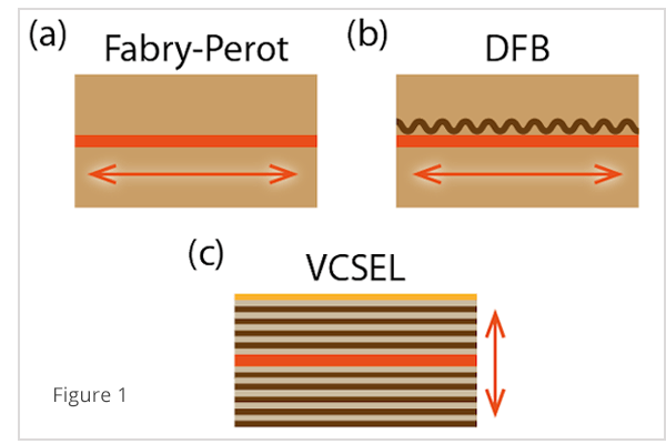
Fig. 1. Types of semiconductor laser diodes most widely used for industrial applications: (a) Fabry-Perot resonator (FP), (b) Distributed Feedback (DFB laser) and (c) Vertical Cavity Surface Emitting Laser (VCSEL). The red region represents the active region of the laser diode. Different colors schematically show the variation of a refractive index in the structure. The arrows indicate the direction of light propagation in the structurse.
OPTICAL FIBER DEVELOPMENT:
Experiments in optical radiation transmission through a glass fiber started in the early part of twentieth century, but losses were too high to allow for practical communications applications. In 1970, Corning Inc. produced optical fiber with optical losses below 17 dB/km, making optical fibers practical for long-range communication. Within a few years, optical losses were further decreased by a factor of 100 and manufacturing methods were developed that made optical fibers a competitive alternative to copper wire for communication systems. Currently, multiple types of quartz-based optical fibers are used: single and multi-mode fibers; polarization maintaining fibers; photonic crystal fibers; spun-fibers; fibers doped with various exotic metal compounds and even hollow-core fibers.
LASER MODULE PERFORMANCE REQUIREMENTS:
Efficient and cost effective coupling of light from a semiconductor laser diode into optical fiber is critically important for practical applications of laser diodes. In an optical lab, it is possible to use a system of lenses and micromanipulators to collimate and focus the laser light a fiber. But in telecommunications, medical, sensor, and commercial applications, the collimating and focusing optics have to be incorporated into the smallest possible package. And these optics need to incorporate all the components required for reliable long-term operation. Laser diode modules are subject to various operating requirement. These include being light weight, compact, having a high optical coupling efficiency and being high stability under vibrations and temperature variations. All of these parameters can be ensured by accurate optical alignment, precision construction of the module, and reliable bonding of the internal components.
COUPLING LIGHT INTO AN OPTICAL FIBER:
In many cases, for a laser diode module to be useful in an application, the light from the laser must be coupled into the optical fiber. When fiber is aligned in a laser diode package, the optical output of the fiber is monitored while the fiber is positioned. The highest coupling efficiency is achieved at the maximum observed ex-fiber power and the fiber is fixed at that point. The coupling efficiency, η, is the ratio of power coupled to the waveguide (PWG) from an incident input source (Pinc):

When coupling light from the laser diode into the optical fiber, several criteria must be satisfied simultaneously. There must be a high coupling efficiency, cost efficient manufacturing and high tolerance for temperature changes and mechanical vibrations. Finally, the coupling must of course achieve a high level of long term reliability. Unfortunately, not all of the radiation coming out of a laser diode couples successfully into the optical fiber (Fig. 2). Part of the light goes outside of the fiber and part of the light enters the cladding and is coupled into the core further at a point further down the fiber than intended. Furthermore, some is reflected from the fiber end.
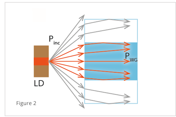
Figure 2. The Losses of Coupling Light into an Optical Fiber
The first method of alignment, developed in the 1990s, was quite complicated and very expensive (Fig. 3). A focusing lens was formed on the end of the fiber by an electric arc discharge and the end of the fiber was covered with a layer of gold. A small ball of solder was deposited on a pillar inside the laser module, and the fiber was held in place in the molten solder puddle until the solder cooled [1]. A typical coupling efficiency by this method was 30–40%. This method was, however, expensive and difficult to implement.
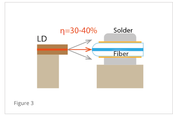
Figure 3. Original Method of Fiber Fixed by Solder
In the late 1990s, a less expensive method was developed using a small ball lens in a protective cap [2] (Fig. 4). This method is fast and simple to implement at a low cost, but the coupling efficiency is only 10% – 20%.
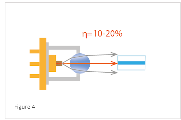
Figure 4. Light Coupling by Ball Lens
In the early 2000s, very small GRaded INdex (GRIN) lenses were implemented for fiber coupling in laser modules [3] (Fig. 5a). Even though laser diodes with such lenses were more expensive, the coupling efficiency increased to about 30%. Unfortunately, such systems were very sensitive to temperature and were restricted to narrow operating temperature ranges. In 2010, aspherical lenses of a more complicated shape and with antireflection coatings appeared on the market (Fig. 5b). Such lenses are presently commonly used in some laser diodes and provide coupling efficiency up to 40%. One disadvantage to both GRIN and aspheric lens coupling is that a separate optical component must be aligned and fixed within the laser module. This increases overall cost and complexity of the finished device.
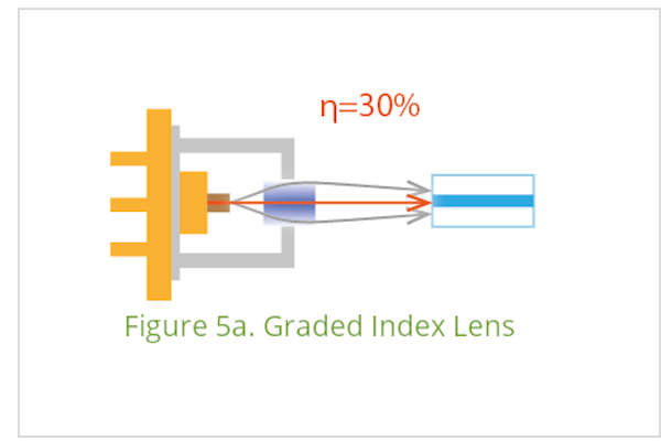
Figure 5A. Laser Diode GRIN Lens
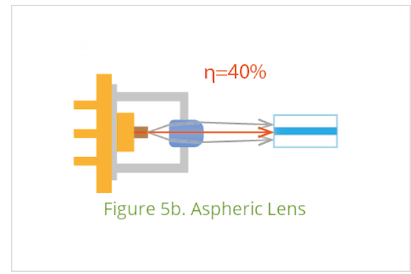
Figure 5B. Laser Diode Aspheric Lens
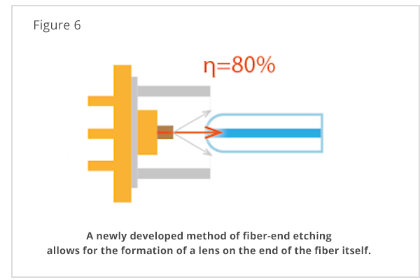
Figure 6. LasersCom LLC employs a method of optical coupling that uses a lens formed on the end of an optical fiber by selective etching (Fig. 6). Selective etching creates a precision-shaped lens that allows coupling efficiency up to 80% in mass-produced modules. This technology does not use a lens as a separate optical element, which makes optical alignment simpler, cheaper, and more reliable. Compared to typical laser diode modules, the coupling efficiency is up to two times larger for optical time-domain reflectometry lasers and up to five times larger for optical communications laser modules. Higher coupling efficiency results in a greater slope of the output PI-curve, and ultimately results in lower power consumption of communications systems.
BONDING INTERNAL LASER DIODE MODULE COMPONENTS:
Long-term reliability and the overall laser diode module efficiency are dependent on the bonding of the internal components. Bonding methods must also be cost efficient. Over time, bonding methods have evolved along with increased performance demands.
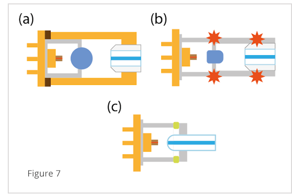
Fig. 7. Laser diode module parts bonding with the help of (a) epoxy glue, (b) laser beam welding, (c) special compound with a small thermal expansion coefficient, the technology employed by LasersCom LLC.
Until the early 2000s, the main method of module parts bonding was epoxy glue [4] (Fig. 7a). Epoxies are temperature sensitive, which causes components to shift over temperature and results in optical parameter fluctuations. Even though working with epoxy glue is convenient and inexpensive, a high percent of devices fail during post-manufacturing thermal cycling and accelerated aging. Further failures can occur after laser module deployment because of epoxy-bonding failures. Starting in the early 2000s, laser beam welding was introduced into laser diode module assembly [5] (Fig. 7b). The manufacturers of the laser diode modules even tried to emphasize in advertisements that the modules did not contain epoxy glue and therefore were more reliable.
Even though laser beam welding has increased the yield of modules, there are manufacturing constraints. The most important is that the welded parts have to be firmly fixed during welding in order to avoid mechanical deformations caused by the high thermal gradient at the weld site [6]. Also, it’s critical to control the influence of welding on the optical parameters of the laser.
The technology employed by LasersCom LLC has a significant advantage by using a special compound with a low thermal expansion coefficient (Fig. 7c). This ensures high strength as well as excellent reliability and thermal stability. All LasersCom modules successfully pass passive thermal cycling from –40 to +85°С.
LASER DIODE MODULE SELECTION CRITERIA:
Significant improvements have been made in laser diode module fabrication over the past 20 years. Light-coupling technologies have been developed with higher and higher coupling efficiency. Also, component bonding methods have evolved to provide very high thermal stability and long device life-times.
One important operating criteria to consider when selecting laser diode modules is the “tracking error” (Er). Tracking error describes the maximum optical power stability over the operating temperature range:
Where T0 = 25°С is the reference temperature, Tmin and Tmax are the minimal and maximal temperatures, respectively. In applications that will experience harsh environmental conditions, the tracking error is critically important since it partly determines the overall stability of the communications system. If the laser module manufacturer doesn’t specify the tracking error, laser modules with a wide operating temperature range should be chosen. Wider operating temperature range specifications indicate greater stability and reliability.
All the modules produced by LasersCom LLC pass strict operating criteria in the temperature range from -20°С to +50°С (LDI labeled modules). Some modules are also specified for operation from -60°С to +85°С (LDS modules). The tracking error Er does not exceed 0.6 dB for LDI modules and does not exceed 0.3 dB for LDS laser diode modules with the wavelength 1270-1650 nm. From 2021 LasersCom is launching the LDS series with the improved thermal stability for the single-mode fiber-coupled modules in the wavelength range from 488nm to 1064nm.
VIEW LASERSCOM PRODUCTS:
References
- [1] W. H. Cheng, M. T. Sheen, G. L. Wang, S. C. Wang, and J. H. Kuang, “Fiber alignment shift formation mechanisms of fiber-solder-ferrule joints in laser module packaging,” J. Light. Technol., vol. 19, no. 8, pp. 1177–1184, 2001.
- [2] R. P. Ratowsky, L. Yang, R. J. Deri, K. W. Chang, J. S. Kallman, and G. Trott, “Laser diode to single-mode fiber ball lens coupling efficiency: full-wave calculation and measurements.,” Appl. Opt., vol. 36, no. 15, pp. 3435–3438, 1997.
- [3] I. Kitano, H. Ueno, and M. Toyama, “Gradient-index lens for low-loss coupling of a laser diode to single-mode fiber,” Appl. Opt., vol. 25, no. 19, p. 3336, 1986.
- [4] M. S. Cohen, G. W. Johnson, J. M. Trewhella, D. L. Lacey, M. M. Oprysko, D. L. Karst, S. M. Defoster, W. K. Hogan, M. D. Peterson, and J. A. Weirick, “Low-Cost Fabrication of Optical Subassemblies,” vol. 20, no. 3, pp. 256–263, 1997.
- [5] J. H. Kuang, “Crack formation mechanism in laser welded au-coated invar materials for semiconductor laser packaging,” IEEE Trans. Adv. Packag., vol. 22, no. 1, pp. 94–100, 1999.
- [6] Y. Lin, C. Eichele, and F. G. Shi, “Effect of Welding Sequence on Welding-Induced-Alignment-Distortion in Packaging of Butterfly Laser Diode Modules: Simulation and Experiment,” J. Light. Technol., vol. 23, no. 2, pp. 615–623, 2005.
- [7] “LasersCom, LLC.” http://www.laserscom.com/.