High Speed Fiber Modulator Basics
Overview of Different Approaches for Laser Modulation
Author: Dr. Sebastien Ermeneux
ALPhANOV
Publish Date: June 2019
INTRODUCTION:
This tutorial provides an overview of the technical approaches most commonly used to change the amplitude (modulation) of laser light in the nanosecond or sub-nanosecond time domain in fiber-coupled laser systems. More specifically, this tutorial gives a summary of the pros and cons of the four primary technical approaches to laser modulation. Three of these are based on external modulation : AOM (Acousto-Optic Modulators), EOM (Electro-Optic Modulators), SOA (Semiconductor Optical Amplifiers) and the fourth is by directly driving the laser diode.
QUICK NAVIGATION:
- ACOUSTO-OPTICS MODULATOR: AOM
- ELECTRO-OPTICS MODULATOR: EOM
- SEMICONDUCTOR OPTICAL MODULATOR: SOM (SOA-based modulation)
- DIRECT LASER DIODE MODULATION
ACOUSTO-OPTICS MODULATOR: AOM
Fiber-coupled acousto-optic devices are available at various wavelengths from 380nm to 2500nm. The major advantage of acousto-optic fiber coupled device modulation is the relatively high optical power these modulators can handle. They are specified to work with power levels which can reach several watts (more than 10W in some cases). However, with acousto-optic modulators (AOM’s), a primary con is the tradeoff between the switching speed and the insertion loss. The more the optical beam is focused within the AOM’s embedded crystal, the faster it switches, but the more difficult it can reach the output fiber without suffering losses.
For more information on this technology, you can read an in-depth overview of acousto-optic theory from AA Opto Electronic.
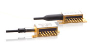
- Figure 1 : Fiber-coupled Acousto-optic modulator from Brimrose (left) and Gooch & Housego (right) – (Courtesy of Brimrose/ Gooch & Housego - websites)
Three highly reputable manufacturers of fiber-coupled acousto-optic modulators are:
- » A&A Optoelectronic : French - based
- » Brimrose : USA - based
- » Gooch and Housego: UK - based
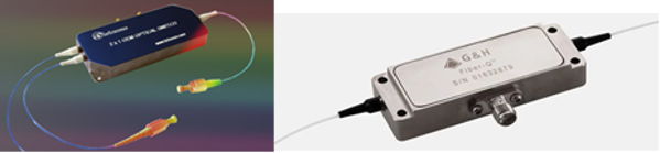
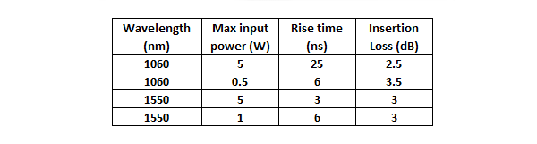
Here are several examples of the key specifications for AOM models available around 1064nm and 1550nm:
When considering the price of an AOM set-up, the user should consider the total cost of the three key elements:
- » The AOM component itself
- » The RF driver
- » The fast switching driving electronics generating 0-1V or 0-5V depending on the RF driver
The RF driver is typically supplied by the AOM component supplier. An example of multi-function, simple to use fast switching driving electronics module is shown in figure 2. This module combines an impressive number of functions including pulse-picking and an AWG. It is manufactured by Alphanov.
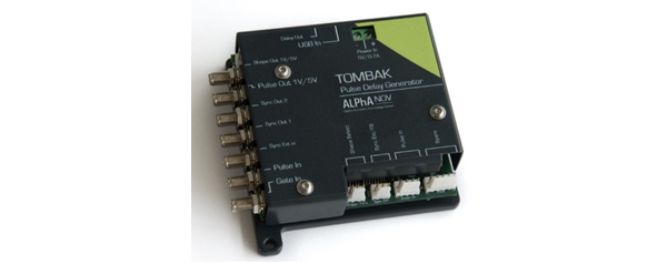
- Figure 2 : Example of fast switching synchronization electronics from Alphanov
ELECTRO-OPTICS MODULATOR: EOM
The major advantage of an electro-optic modulator (EOM) is their bandwidth, which extends into the 10’s of GHz range. Keep in mind that the user must find the driving electronics to support this bandwidth.
- Figure 1 : Fiber-coupled Acousto-optic modulator from Brimrose (left) and Gooch & Housego (right) – (Courtesy of Brimrose/ Gooch & Housego - websites)
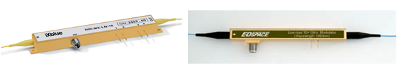
Four highly reputable manufacturers of fiber-coupled electro-optics modulators are:
- » iX-Blue : French - based
- » EOspace : USA - based
- » Jenoptik : Germany - based
- » Thorlabs : USA - based
Several difficulties which are associated with electro-optic modulator (EOM) can be solved by increasing the complexity of the overall setup. If you decide to utilize an EOM based modulation setup, there are several parameters which need to be considered and correctly managed:
» Insertion loss : Insertion loss levels vary from one model to another. In general, improving one key performances attribute of an EOM (ie extinction ratio) can have a negative consequence on the insertion losses. Typical insertion losses are in the range of 4-5 dB.
» Maximum input/output power : Typical maximum input power is in the range of 50mW (17dBm). This maximum power is generally an average power. One can thus overcome this limit / problem by applying a pulsed signal at the input fiber instead of a CW signal. The modulated input signal can be generated by an AOM (refer to AOM overview above) or by directly modulating the laser diode. This, however, produces some other difficulties associated with the stability of the V-bias (see below).
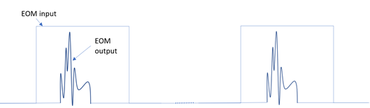
- Figure 4 : Example of a pulsed configuration to overcome the average input power limitation of EOMs
» Stability of V-bias : This is one of the most difficult technical issues to manage when using an EOM. EOM’s generally drift because of thermal inhomogeneity etc. This causes the transfer function (see Figure 5) to move in the horizontal direction and the modulation signal is applied to a changing operating point. This can affect the quality of the modulation.

- Figure 5 : Transfer function of an intensity modulator
In order to operate the intensity modulator and obtain the desired modulation, the user must apply two separate voltages to the modulator: (1) A modulation voltage V(t) and (2) a DC voltage (also called V-bias). The bias voltage selects the desired operating point and compensates for the drift in order to keep more stable operating conditions.
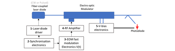
- Figure 6 : A typical setup for driving an EOM requires 5 types of electronics :1- laser diode driver, 2-global synchronization, 3-fast modulation, 4-RF Amplifier, 5-Vbias electronics
Many suppliers offer the laser diode driver described in the block diagram above. Finding a pulser which will generate stable, clean pulses in the nanosecond time domain is important. Here is an example of a well specified laser diode pulse driver :

The product show in Figure 2 can be efficiently used as a the second “synchronization” electronics source which is referred to in Figure 6.
Another Alphanov product worth mentioning combines the three first electronics functions above with very good technical performance (see figure 7). This pulse driver is able to drive and control a butterfly laser diode, generate several synchronization signals and drive the EOM with a programmable pulse shape with a temporal resolution down to 500 picoseconds.
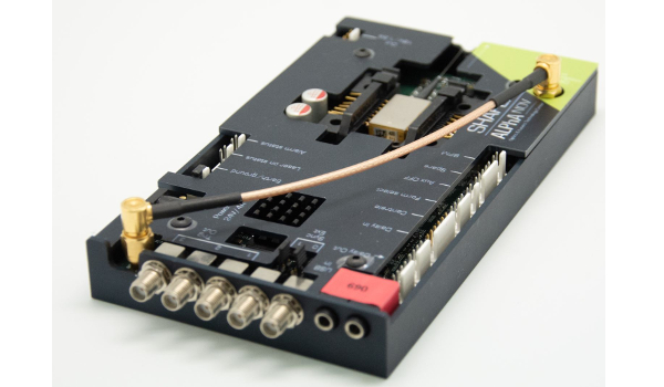
- Figure 7 : Shaper board for EOM driving, combining a laser diode driver, a multiple output synchronization electronics and a 5V programmable shape output to drive an EOM with 2GHz bandwidth and 48dB dynamic range
The fifth block shown in Figure 6 is very important when high stability is required (which is most often the case). Here are three products which are available from highly reputable manufacturers:
- » Analog MZ Modulator Bias Controller from iX-Blue
- » PuLse MZ Modulator Bias Controller from iX-Blue
- » Mini-MBC from YY-labs
A major difficulty associated with the setup shown in Figure 6 occurs when a user needs to operate with a pulse regime at very low duty cycle. The low level of power might not be enough for the V-bias electronics to be able to keep control of the bias level. The difference between the electronics product generations plays an important role here.
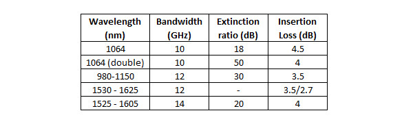
Some examples of a few key technical parameters of EOM models available around 1064nm and 1550nm are shown in the table below:
SEMICONDUCTOR OPTICAL MODULATOR: SOM (SOA-based modulation)
Semiconductor optical amplifiers (SOA) are a well-established alternative to CW EDFA’s (Erbium Doped Fiber Amplifiers) and are used to amplify a pulsed signal. A Semiconductor optical modulator (SOM) utilizes SOA technology in a different way than traditional SOA amplifiers have been used (Figure 8). Semiconductor optical modulation utilizes a SOA as a light modulator with potentially negative insertion loss (ie Gain). In this case, a CW laser diode signal is applied to the SOA and it is the level of current driving the SOA which is switched ON/OFF at GHz speed. This modulated signal can also be customized and shaped to accommodate many emerging applications.

- Figure 8 : SOA, when driven with a specific electronics, behaves like a fiber modulator with no insertion loss (SOM)
There is a number of advantages to use SOA compared with other solutions :
- » The dynamic range of an SOM is much higher than that of an EOM or an AOM. An AOM or EOM are typically limited to < 30 dB, and often less since there is a strong polarization dependency.
- » An SOM has no polarization rotation dependencies, whereas both an EOM and an AOM typically are susceptible to polarization dependencies.
- » The spectrum of an SOM remains the same along the entire pulse, whereas when directly pulsing a laser diode, the user must consider the undesirable spectral effects which can occur from coupling of the frequency/phase spectrum and intensity profile.
- » The spectrum of an SOM remains the same along the entire pulse, whereas when directly pulsing a laser diode, the user must consider the undesirable spectral effects which can occur from coupling of the frequency/phase spectrum and intensity profile.
One needs, however, to pay attention at two important characteristics :
- » The high extinction ratio is polarization dependent and it is often necessary to add a polarizer (or isolator for its polarizing properties) at the output to reach the very high extinction ratio levels.
- » Depending on the configuration and input laser diode power, one may want to take advantage of the ability of the SOA to amplify the input signal. This is potentially interesting, but this also can generate a small ASE signal. An ASE filter might be pertinent in some integration configuration.
Several highly reputable suppliers of SOA’s :
- » Innolume for SOA ranging from 950 to 1300nm
- » Thorlabs at discrete wavelengths like 1050 or 1550nm

- Figure 9 : Example of SOAs with high extinction ratio (Courtesy of Innolume / Thorlabs - web sites)
When using an SOM, extinction ratios as high as 70 dB are possible. The maximum input power is generally not much higher than the saturation output of typically 50mW (17 dBm).
Alphanov offers an open-frame driver and control module which is compatible with the pin configurations and the package size of most commercially available SOA’s:
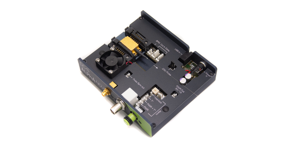
- Figure 10 : Alphanov SOA driver able to modulate light down to 1ns with very high extinction ratio of more than 50dB.
Alphanov offers a complete SOM turn-key solution. This SOM is offered with a broad selection of SOA’s from 775nm to 1625nm. Current and temperature control circuits and safety limits are pre-set and optimized to ensure the highest level of performance in pulsed mode.
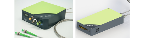
- Figure 11 : Turn-key SOM with several interesting functionalities and USB control. Square shape version (left) : The pulse width can be adjusted internally or triggered externally with a LVTTL signal. The peak power is adjusted internally with up to 60dB resolution or externally with a pure analog 0-5V signal. Shaped version with internal AWG (right) ; the shape of the output pulse can be configured with 2GHz bandwidth and 48dB dynamic range.
DIRECT LASER DIODE MODULATION
The last (but not least) solution for modulating the light coming from a fiber-coupled laser diode is to apply a direct modulation using a pulse control electronics current driver. An example of a 3 nanosecond pulse width is shown below. One can see the gain switch peak at the beginning of the pulse. This is a relaxation of the carrier within the laser diode. Gain switch peaks can be useful if one wants to isolate this gain switch peak pulse and get ~ 100 picosecond pulses. But the gain switch peak is typically an undesired property.
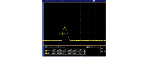
- Figure 12 : 3ns stable pulse width from the direct pulsing of a DFB Butterfly laser diode with Alphanov CCS driver.
There are fewer than 10 companies around the world who specialize in manufacturing commercially available laser diode pulse drivers. However, the pulse shape at a short pulse width and the rise/fall time and Jitter levels can be very different from manufacturer to manufacturer. Also, there are many key features and additional functions which vary from each manufacturer, and ease of use should also be considered.
The bandwidth limitations are a result of the speed of the electronics on the “drive side” and the inductance of the laser diode on the other side. Reaching a 5 nanosecond per amp rise/fall time is possible in an ON/OFF switching mode from many suppliers. However, combining modularity, ease of use and high performance levels is the most difficult part when developing a pulsed driver.
Alphanov offers two ON/OFF laser diode switching driver models with switching speed from 3 nsec/A to less than 0.5nsec/A.
Another high performance product for direct laser diode modulation is called a “Pulse-Shaper”. It is the same product shown Figure 7, but configured for direct laser diode current shaping. It includes an internal AWG and is able to shape the laser diode output with 48dB amplitude resolution and 500 picoseconds of timing resolution.
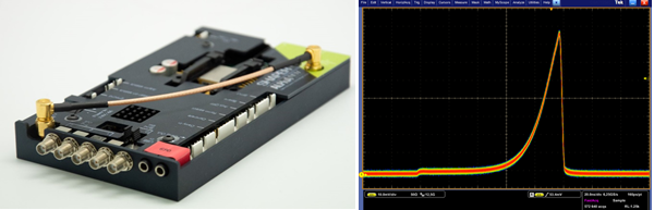
- Figure 13 : Alphanov shaper module set in direct driver configuration (left) and special optical pulse shape obtained from a DFB laser diode after its programmed within the module (right)
This pulse-shaper module allows the user to program a customized shape with a high bandwidth AWG and generates the desired custom optical pulse shape. As seen in the figure bellow, this module also has a special internal function which allows the user to mitigate the gain switch peak :
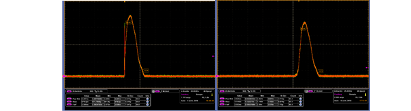
- Figure 14 : 3ns pulse shapes out of a DFB laser diode driven by Alphanov shaper modules. The left curve has a gain switch peak which is suppressed on the pulse on the right by activating the internal “gain switch peak suppression” function.
CONCLUSION
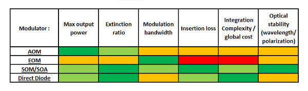
The table below summarizes the pros and the cons of the various solutions. AOMs are interesting when looking for several Watts of output power. EOMs are the fastest solutions despite a high level of integration complexity and low extinction ratio. SOM (i.e. SOA used in a modulator configuration with a special electronics) has clearly major advantages when looking for a cost-effective GHz speed solution. Direct laser diode is the cheapest solution but be careful that the wavelength will shift all along the pulse and one needs to choose the good driving electronics to reach a minimum peak power when looking for less than 10ns pulse width.